48+ Carey Foster Bridge Diagram Images
48+ Carey Foster Bridge Diagram Images. In electronics, the carey foster bridge is a bridge circuit used to measure medium resistances, or to measure small differences between two large resistances. Determination of the resistance per unit length of the carey foster's bridge wire.
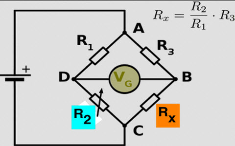
End resistance arises out from the resistance of copper strip,the resistance at the junction bridge wire with the copper strips.carey foster bridge can measure low and high resistance more.
The circuit used a power supply. In electronics, the carey foster bridge is a bridge circuit used to measure medium resistances, or to measure small differences between two large resistances. It was invented by carey foster as a variant on the wheatstone bridge. It can be used to find out the average resistance per unit length of the meter bridge wire and hence find out the unknown resistance.
Posting Komentar untuk "48+ Carey Foster Bridge Diagram Images"